Module 4EncoderMotor V1.1
SKU:M138-V11
Description
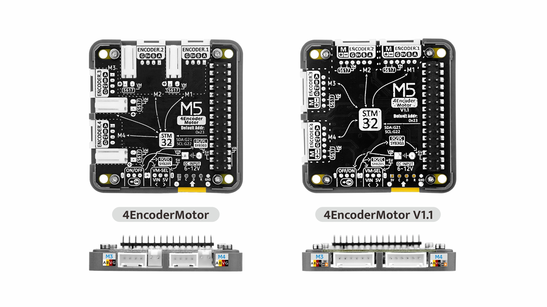
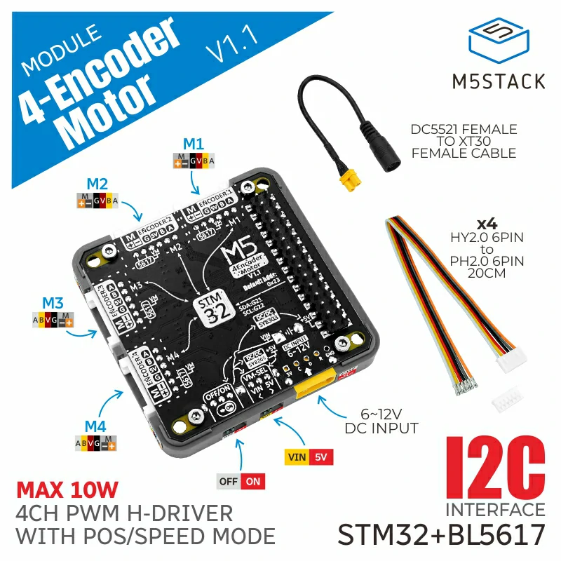
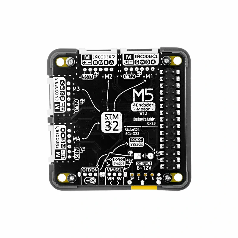
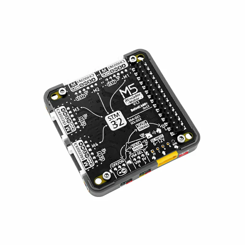
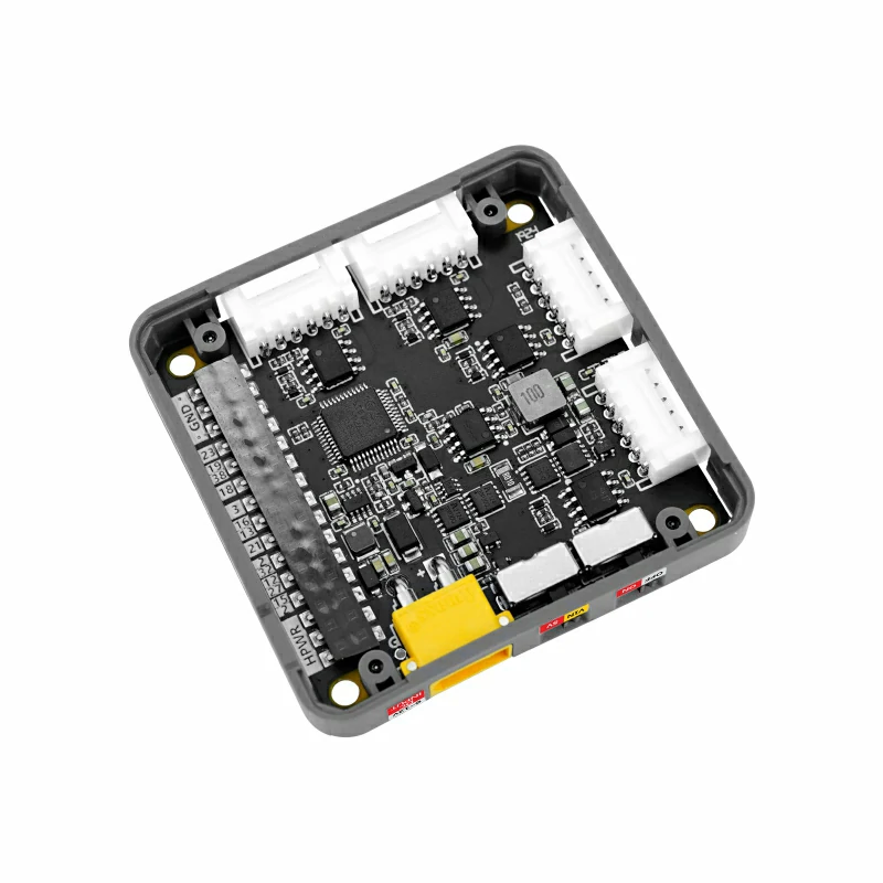
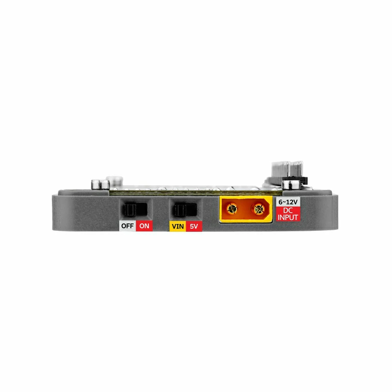
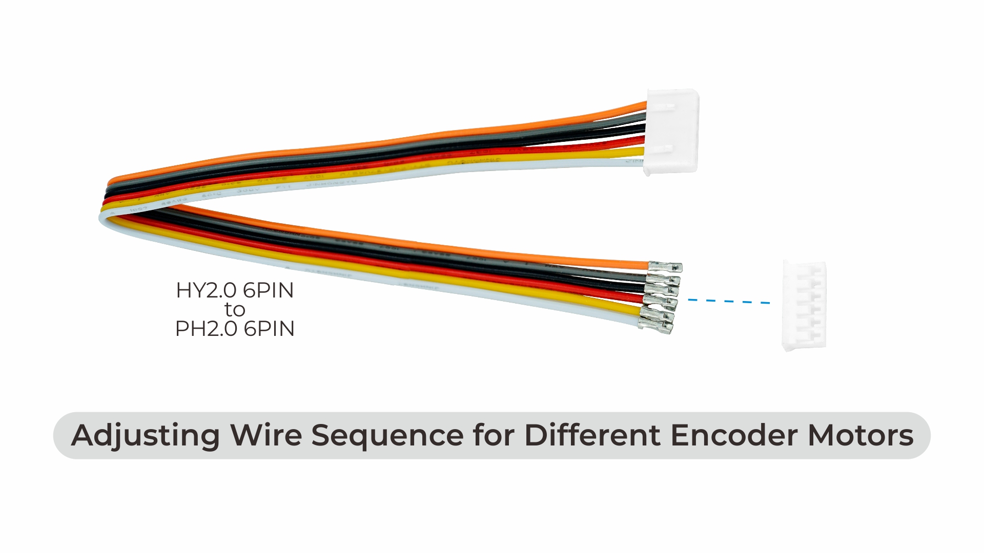
The 4EncoderMotor Module V1.1 is a 4-channel encoder motor driver module that employs an STM32 + BL5617 H-bridge driver IC solution. It utilizes I2C communication, supporting slave address modification to provide flexible control options. The module accepts AB pulse encoder signal input, enabling precise motor motion state and position detection. It supports various modes such as duty cycle control, absolute position positioning, and speed adjustment to achieve motor forward, reverse, stop, and brake functions. The integrated INA199 power monitor allows real-time monitoring of current status. The onboard power input switch allows selection between DC 5V or external DC 6-12V power input. Compared to the previous 4EncoderMotor Module, this product has undergone interface optimization, adopting a unified HY2.0mm-6P interface. This design simplifies the wiring process, enhances ease of use, reduces the number of interfaces, and improves overall system reliability. The 4EncoderMotor Module V1.1 is suitable for applications in robotic motion control, automation equipment, intelligent vehicles, laboratory devices, and industrial automation systems.
Features
- 4 channel coded motor drive
- Duty cycle, absolute position positioning, speed adjustment control mode
- I2C communication mode
- The voltage input terminal and current monitoring (for motors)
Includes
- 1x 4EncoderMotor Module V1.1
- 4x HY2.0-6P Single-ended Cable(20cm)
- 4x PH2.0-6P Connector
- 1x DC5521 Female To XT30 Female Cable
Applications
- Robot motion control
- Automation equipment
- Industrial automation system
Specification
| Resources | Parameters |
|---|---|
| Encoder Motor Driver IC | BL5617 |
| Power supply detection chip | INA199 |
| Maximum Supported Current | 3.0A |
| Power | Max 10W |
| External DC Power Supply | 6-12V |
| I2C Communication Address | 0x24 |
| Standby Current | DC6V@35.03mA DC12V@19.25mA |
| Operating Temperature | 0-40°C |
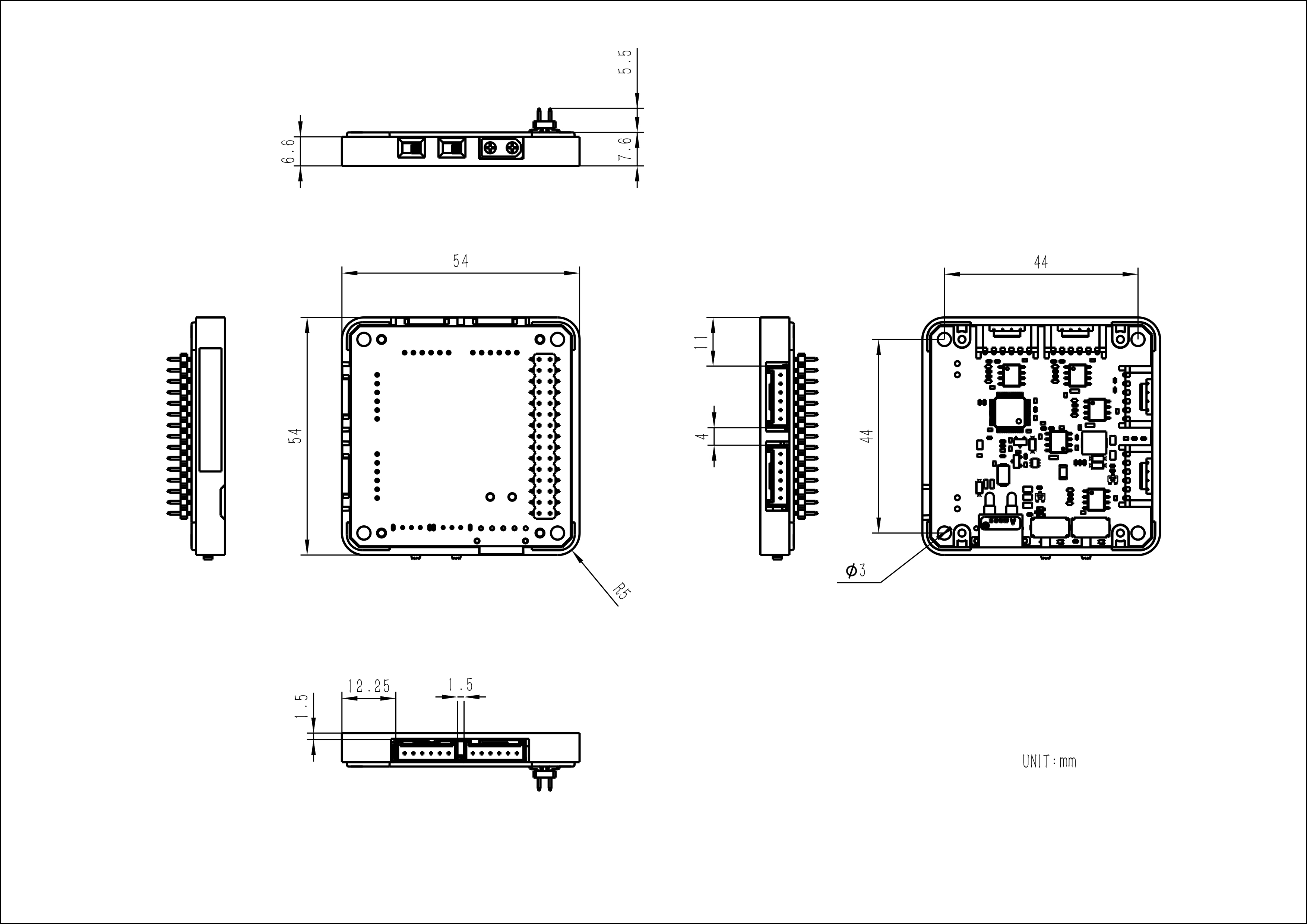
| Product Size | 54*54*13.1mm |
| Package Size | 94*67*25mm |
| Product Weight | 15.9g |
| Package Weight | 57.1g |
Related Link
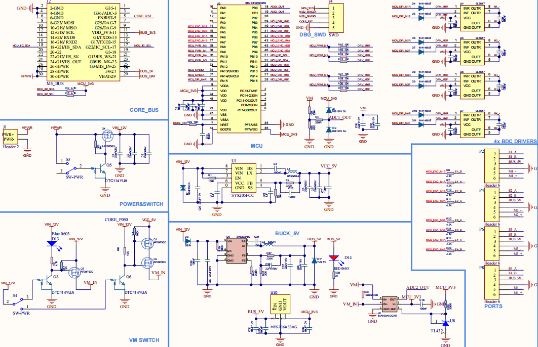
Schematic
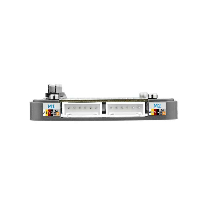
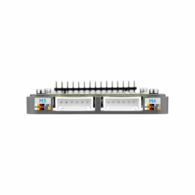
Example of coding motor wiring
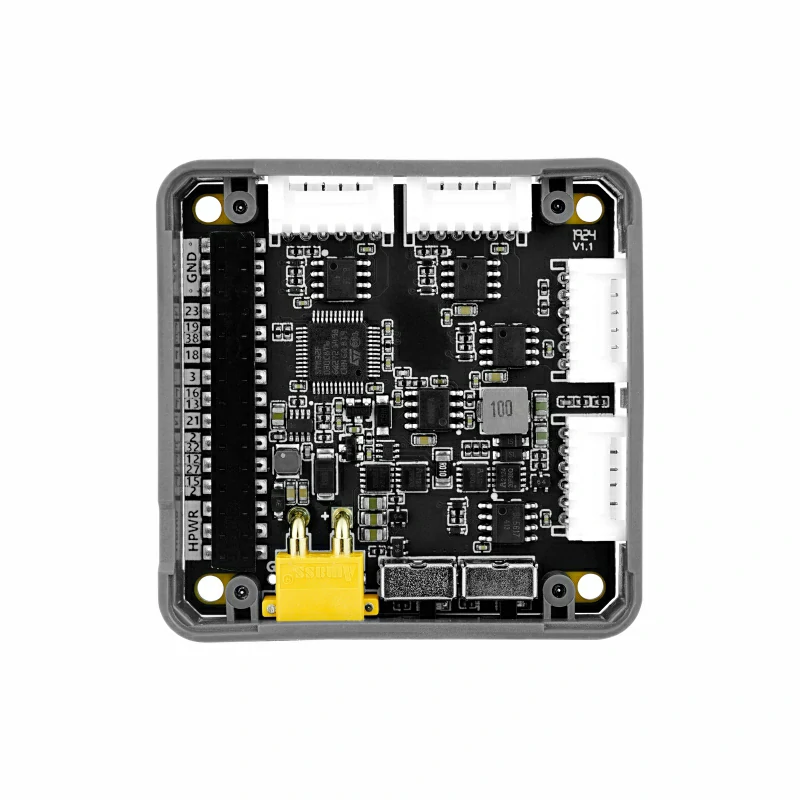
PinMap
I2C communication and current and voltage detection
| STM32 | MCU_IIC_SDA(PB11) | MCU_IIC_SCL(PB10) | PB0 | PB1 |
|---|---|---|---|---|
| Core(Basic) | G21 | G22 | ||
| Core2 | G21 | G22 | ||
| CoreS3 | G12 | G11 | ||
| Motor Voltage Detect | ADC1_OUT | |||
| Current Detect | ADC2_OUT |
Code motor direction control pin
| STM32 | PB14/PB15 | PB12/PB13 | PB4/PB5 | PA15/PB3 |
|---|---|---|---|---|
| BL5617 (Direction) | MCU_DIR_M1R/MCU_DIR_M1F | MCU_DIR_M2R/MCU_DIR_M2F | MCU_DIR_M3R/MCU_DIR_M3F | MCU_DIR_M4R/MCU_DIR_M4F |
Code motor speed PWM control
| STM32 | PA9 | PA8 | PA11 | PA10 |
|---|---|---|---|---|
| BL5617 (PWM) | MCU_PWM_M1 | MCU_PWM_M2 | MCU_PWM_M3 | MCU_PWM_M4 |
Coding motor A/B signal detection
| STM32 | PA6/PA7 | PA4/PA5 | PB9/PB8 | PB7/PB6 |
|---|---|---|---|---|
| Encodering motors | E1_A/E1_B | E2_A/E2_B | E3_A/E3_B | E4_A/E4_B |
Module Size
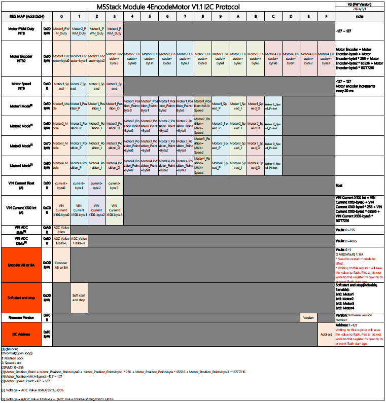
Protocol
Examples
Arduino
- M5Module-4EncoderMotor V1.1 Library
- M5Module-4EncoderMotor V1.1 For Basic
- M5Module-4EncoderMotor V1.1 For Core2
- M5Module-4EncoderMotor V1.1 For CoreS3
Video
Version Comparison
| Product | Communication Protocol | Chip Scheme | Control Motor Type | Channels | Control Mode | Remarks |
|---|---|---|---|---|---|---|
| 4EncoderMotor Module (M138) | I2C (0x24) | STM32 + BL561 | DC Motor/Encoder | 4 | Duty cycle, absolute position, speed, adjustment control mode | |
| 4EncoderMotor Module (M138-B) | I2C (0x24) | STM32 + BL561 | DC Motor/Encoder | 4 | Duty cycle, absolute position, speed, adjustment control mode | M138-V11 compared to M138 modifies the encoder motor interface to HY2.0-6P Grove interface |
| DC Motor Module (M021) | I2C (0x56) | MEGA328 + L29 | DC Motor/Encoder | 4 | Speed adjustment control mode |